As for the installation and connection mode of encoder, we have found a brief introduction of coupling, direct connection and flange installation on the Internet for your reference. You can determine the installation and connection mode of encoder according to your actual needs.
Encoder is a small part in a complex system. It can help manufacturers produce high-quality parts or move objects from point A to point B quickly and smoothly. If you decompose the system, its main components include 1 motor, 1 driver or amplifier, possibly 1 brake and 1 encoder. The encoder is the most troublesome during installation. This article will introduce different encoder installation methods and their advantages and disadvantages from the perspective of space, surrounding environment and mechanical factors, as well as the consequences of incorrect installation.
Encoder is a component in the motion control system, which is used to feedback signals to the driver for accurate speed and position control. Encoder selection seems to be a difficult task. Mainstream encoder manufacturers are constantly releasing new encoder series, making the product line increasingly large, and the options of the same series of products are also increasing.
Although the interface and electrical options of each encoder series seem complicated, the choice is still yours. When you select a drive, the drive parameters will contain appropriate input options, and the encoder must be selected according to these options. The installation mode is the most important point of the uneven encoder. Reasonable selection of installation mode can improve the life and performance of the encoder at the same time. If you want to do a good job, you must first make use of the tools, and the appropriate installation options are just like the appropriate "tools".
If flange or foot-mounted encoder is selected, the encoder can be installed on the motor by using 1 coupling and 1 adapter. The coupling is fixed with each shaft by the set screw, and is equipped with a spring or mechanical device to eliminate the impact, vibration or deviation from the motor shaft. This connection mode is very common when the encoder is paired with the old and non-standard motor, and the encoder has no O-ring or hollow shaft model, so it is difficult to compensate for the excessive movement of the motor shaft.
The foot installation is also to install the encoder directly on the motor shaft or through the belt drive. The reason for selecting this method is the same as the reason for selecting the flange installation method. However, in this installation mode, the encoder body is not directly or indirectly installed on the surface of the motor, but is installed horizontally as the motor. Foot-mounted encoders also generally have a Nema56C surface, which is used to mount a gear set or another annular encoder.
Benefits of using couplings
There are many advantages of using couplings to isolate the encoder. This installation method can usually be electrically isolated from the motor. When there is no electrical isolation, the encoder is easily affected by the induction current from the motor power supply and the motor. If there is electrical noise, the encoder output may lose pulse, increase pulse, or even damage the encoder. Mechanical isolation is another benefit. The elastic coupling can absorb the shaft end offset, and can install the encoder on the old motor or the motor working under high impact and vibration conditions.
Precautions for using coupling
The disadvantages of using couplings are mainly mechanical. The primary disadvantage of using a coupling is that it increases the length of the shaft. Considering the clearance between bracket, shaft and coupling and encoder housing, the length of motor shaft will increase by about 7 inches after installing the coupling. In addition, installing the coupling also requires several steps (i.e. shaft alignment and fastening connection).
When installing the coupling, any form of misalignment error in Figure 3 will bring undesirable consequences that we do not want to see. Most importantly, the coupling is subject to stress that could have been avoided. These stresses will eventually cause the coupling material to tear or damage.
Finally, the misalignment error may affect the speed feedback. This effect is similar to the output speed of the shaft driven by the universal joint, as shown in Figure 4. Fluctuation of speed may cause drive failure or product damage due to excessive vibration.
Direct connection installation of spring plate
The encoder is directly installed on the motor shaft through the spring plate. The encoder has its own bearing, so it does not need mechanical alignment. The encoder also has a rod or plate spring plate, which can be fixed on the motor surface or other fixed parts by screws to keep the encoder body from rotating. The motor is driven by different power supplies, and different power supplies will generate different types of current at the shaft and bearing. To protect the encoder and motor bearing, plastic bushing is usually used to isolate the direct-connected encoder shaft between the motor and the encoder shaft. Encoder without plastic bushing or insert shall be grounded through motor shaft or other shaft grounding kit.
Advantages of direct-connected encoder
The direct-connected connection scheme makes it easier to install the encoder on the motor shaft reasonably. When the ring type installation method is adopted, the accurate size information of the motor surface is required. The slotted spring plate can even be installed on the shaft with variable radius. The sensor shaft does not need to be aligned during installation. This means that as long as the shaft sleeve is tightened, the installation work on the shaft is completed. There are plastic bushings or plastic fasteners in the encoder, which can prolong the bearing life, thus saving the cost of motor and encoder. The spring plate can absorb the impact of sudden movement of the motor shaft. This is another design that can extend the life of encoder bearing.
Precautions for direct-connected installation
The housing of the direct-connected encoder usually has a large moving shaft. This means that the contact area of the internal circuit of the encoder is larger than that of the coupling type encoder. The annular encoder (section 4) has no contact on the whole shaft. Encoder manufacturers are constantly adopting new methods to improve this problem. One method is to use labyrinth seal.
It is recommended to slide the encoder on the shaft with both hands or a balancing fixture. In order to extend the service life of the spring plate, the encoder should also be installed in the best position. Figure 5 shows the balanced installation position. Because the encoder hole is intentionally too large, when installing the encoder, if you press a point on the encoder housing hard, the encoder will be warped at a certain angle. This will produce certain stress on the spring plate, as shown in Figure 6. At the same time, under the cyclic action of motor rotation, this stress point will lead to metal fatigue, both stress and fatigue will eventually lead to damage or tear at this point.
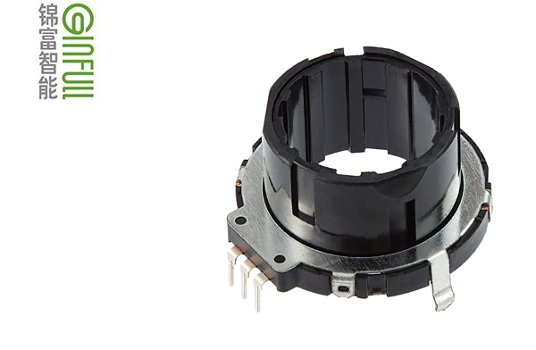
Ring mounted encoder
The ring-mounted sensor includes at least two main components: sensor ring and magnetic grating drum. The sensor ring is installed at the drive end or accessory end of the motor, and the size of its guide cylinder conforms to NEMA or IEC standards. Then put the magnetic grid drum on the shaft, adjust its position with the sensor in the sensor ring, and finally fix it.
Since the movement of the magnetic grating drum in the ring is read by a separately installed part, and there is no mechanical connection between them, the circuit part of the sensor can be sealed. This is an improvement compared with the direct-connected sensor. The circuit tightness of the direct-connected installation depends on the contact tightness of the connector and the shaft gasket. This type of sensor is most commonly used in the paper industry where the paper fiber or dust in the air is easy to accumulate or in machines that need washing. The annular encoder generally adopts magnetic technology, which is hardly affected by liquid. This means that the moving parts of the encoder can be partially or completely submerged in water.
The ring encoder does not have bearings. There is a certain gap between the magnetic grid drum and the annular shell. For coupling mounted or direct-connected encoders, instantaneous impact is likely to cause serious damage, because its shape and bearing preload are critical to signal quality. The slight movement of the motor shaft during rotation will not cause spring force on the bearing, nor will it cause fatigue of the spring plate or coupling. In addition, the annular encoder occupies less space on the motor shaft. They are directly mounted on the surface of the motor, and the other side of the encoder can also be used as the mounting surface of the brake or gearbox.
Precautions for installation of annular encoder
The alignment between the magnetic grating drum and the sensor should be considered first when selecting this kind of encoder. This problem will not occur in coupling type or direct-connected type encoder, because the manufacturer has aligned the sensor. The signal quality of the ring encoder depends entirely on the ability of the installer to correctly align the magnetic grating drum. The magnetic grid drum may appear to be aligned, but once the shaft starts to rotate, it may lose alignment. It must be ensured that the magnetic grating drum of the encoder is in the center of its radial and axial movement. Different manufacturers will provide different operating instructions to guide the installation personnel in alignment. If the above operations are completed correctly and the working environment meets the requirements, the encoder can basically run for many years.
Coupling, direct connection and flange installation are the main encoder installation methods in motor feedback applications. According to the installation environment, the service life of the motor and the installation regulations of the application itself, the three installation methods have their own advantages.


 WeChat